Six hydraulic pumps feed fluid at up to 3,400 PSI to all cylinders and wheel drives.
Flow to the cylinders is controlled with proportional valves.
HYDRAULIC ENGINEERING
Six hydraulic pumps feed fluid at up to 3,400 PSI to all
cylinders and wheel drives.
Flow to the cylinders is controlled with proportional valves.
![]()
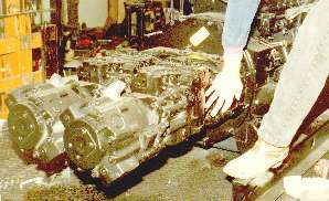
FIGURE 6a. Hydraulic Pumps
The two rows of Parker PAVC 100 pumps and wheel drive pumps were attached in line to the Cummins 444B output drive shaft using a bolt-on gear splitter.
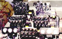
FIGURE 6b. Hydraulic Controls
Close up of left and right banks of Parker HPI proportional control valves and the basic instrumentation (pressure, temperature and wheel drive supercharge pressure) for both banks.
FIGURE 6c. Hydraulic System Details
Note: 1) filtration protection on both the pressure and suction sides; 2) the crossover valve, which in conjunction with the respective check valves, enables a show to continue in the event of an open loop pump failure; and 3) fluid reservoir volume is 500 gallons.
![]()
![]()
![]()
Page 6